How Does A Voltage To Frequency Converter Work
The first pulse loads the data from the CD4040 into the DAC the pulse. The first pulse loads the data from the CD4040 into the DAC the pulse.
The first design is using the IC VFC32 which is an advanced voltage to frequency converter device from BURR-BROWN specifically designed to produce an extremely proportional frequency response to the fed input voltage for a given voltage to frequency converter.

How does a voltage to frequency converter work. First the alternating current power source is rectified into a DC voltage. The operational amplifiers are used for signal processing. The most basic principle of electric frequency conversion can be broken down into two parts.
He built it up and it worked. It is ideally suited for use in simple low-cost circuit for analog-to digital. Its fairly easy to convert AC current to DC all you need to do is feed the current through a diode which only passes current in one direction.
A voltage to frequency converter circuit converts a proportionately varying input voltage int a proportionately varying output frequency. Converting from DC to AC is more complicated because you need some kind of oscillator that reverses the current direction at the frequency you need. In this case the frequency inverter transforms an AC current with a certain fixed frequency into a voltage with variable amplitude and frequency.
This voltage-to-frequency converter provides the output pulse train at a frequency precisely proportional to the applied input voltageThe KA331 can operate at power supplies as low as 40V and be changed output frequency from 1Hz to 100KHz. A frequency inverter is an electronic device which enables the conversion of an electrical variable current. Voltage to frequency converter is simply a electronic conversion mechanism that converts voltage into frequency or we can define voltage to frequency converter as s an electronic device that converts alternating current AC of one frequency to alternating current of another frequency.
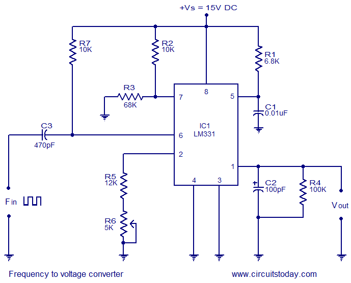
Theres a way to do this mechanically but most inverters rely on resistors capacitors transistors and. This Frequency-to-Voltage converter settles in one cycle of the frequency and uses only a small number of parts. When operated as a VF converter the transformation fromvoltage to frequency is based on a comparison of input signalmagnitude to the 1 mA internal current source.
Voltage To Frequency Converter - YouTube. The digital logic generates a couple of pulses at the time of each rising edge of the incoming frequency you could use some kind of dual one-shot multivibrator but I didnt have any of those around. FREQUENCY TO VOLTAGE CONVERTER CIRCUITS Frequency to voltage converter is an electronic device which converts the sinusoidal input frequency into a proportional current or output voltageThe basic circuit includes operational amplifiers and RC circuits Resistor Capacitor networks.
The digital logic generates a couple of pulses at the time of each rising edge of the incoming frequency you could use some kind of dual one-shot multivibrator but I didnt have any of those around. How Does a Frequency Converter Work. This Frequency-to-Voltage converter settles in one cycle of the frequency.
Besides that it uses only a small number of parts. In short this results in a voltage conversion. Then this DC voltage is chopped into an alternating current voltage of a new desired frequency.

Frequency To Voltage Converter Circuit Voltage Converter Circuit Electronics Circuit
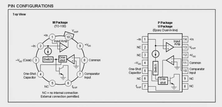
2 Simple Voltage To Frequency Converter Circuits Explained Homemade Circuit Projects
Voltage Into Frequency Converter Circuit Using 741 Ic Engineering Projects
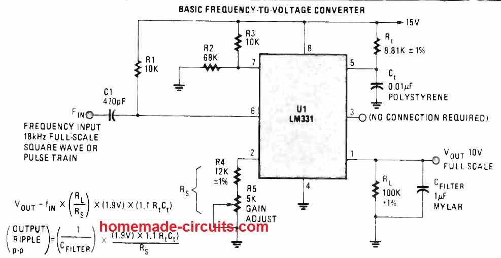
3 Frequency To Voltage Converter Circuits Explained Homemade Circuit Projects
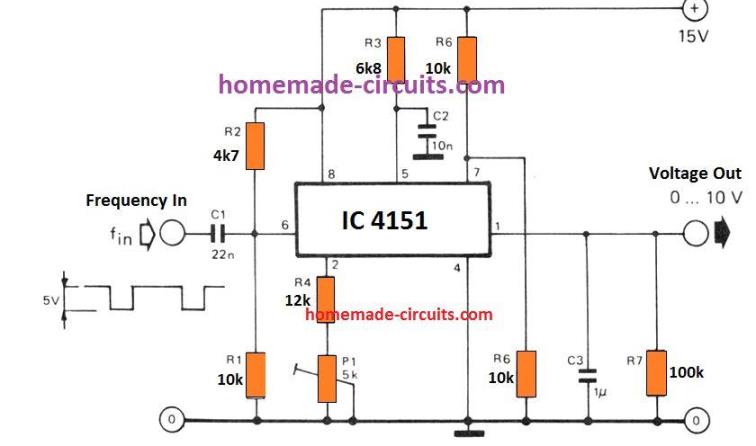
3 Frequency To Voltage Converter Circuits Explained Homemade Circuit Projects
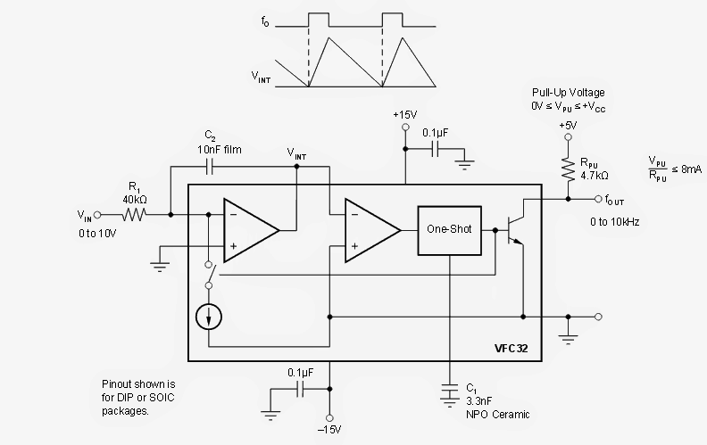
2 Simple Voltage To Frequency Converter Circuits Explained Homemade Circuit Projects
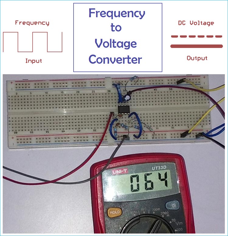
Frequency To Voltage Converter Circuit Diagram

Voltage To Frequency Converter Circuit Using Ca3130 Basic Electronic Circuits Electronics Circuit Electronic Circuit Projects
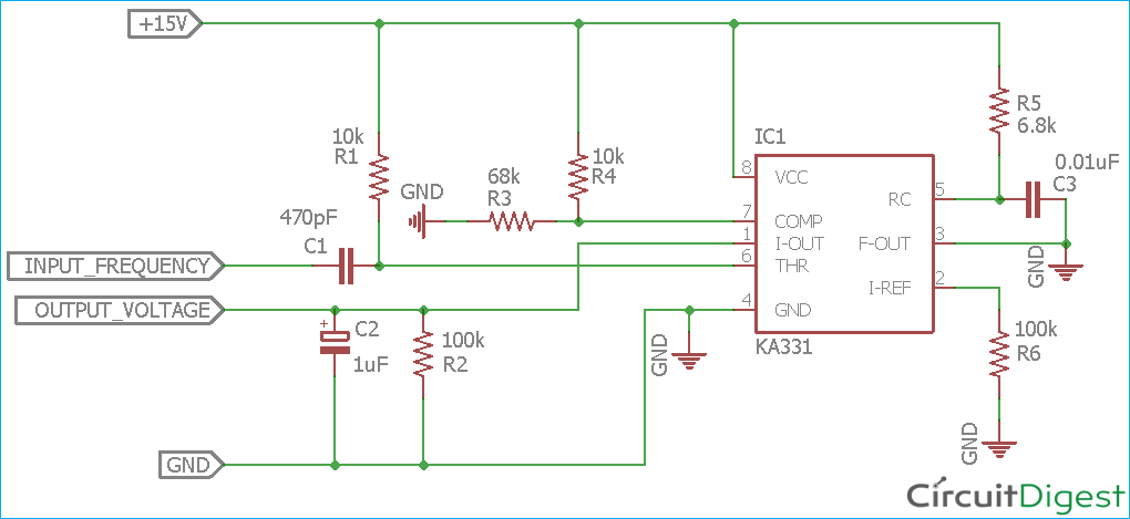
Frequency To Voltage Converter Circuit Diagram

0 75kw 220v Variable Frequency Inverter Controller Single Phrase Frequency Conve Us 95 99 Power Inverter St Kitts And Nevis Converter
Frequency To Voltage Converter Circuit Diagram

Frequency To Voltage Converter Circuit Diagram Applications Of Fv Converter Applications And Analog To Digital Converter Circuit Electronic Circuit Projects
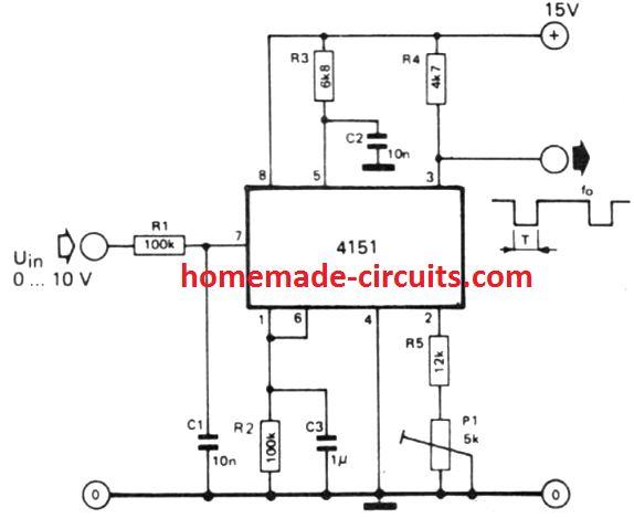
2 Simple Voltage To Frequency Converter Circuits Explained Homemade Circuit Projects

Frequency To Voltage Converter Circuit Diagram
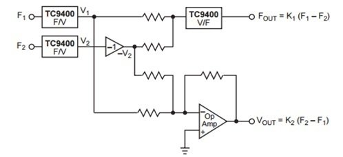
Frequency To Voltage Converter Circuit Diagram

Post a Comment for "How Does A Voltage To Frequency Converter Work"